| |
The model 2008 firstly should be a trailer for the Buessing 8000. But the required
wheels currently are not available from CONRAD, so this project is still to be
postponed - questionable is, however, whether the wheels will be offered ever again.
Instead another axial motor was built, this time in the form of a 2 cylinder steam
engine with link motion.

An opened cylinder
|
Into each of the generously dimensioned cylindes 2 MAERKLIN coils were installed, which
are switched alternately and whose cores work agains each other.
This configuration generates a bi-directional force, giving the behavior of a real steam
engine.
|
Quite time-consuming was the exact alignment of the coils to achive a possibly low-friction
movement of the paired iron cores; each marginal clamping would significantly affect the
function of the machine.
The iron cores themselves are coupled by threaded rods with an appropriate length.
The cover of the cylinders are realized by corrigated card which is excellent qualified for
this purpose.
Due to the 2 cylinders with a total of 4 coils and 90° shifted crank pins the engine
theoretically is self starting. But the bearings of the lot of movable parts cause a
significant friction and so the self start does not work reliable.
For the purpose of low friction forces even at this model some aluminium parts were used,
such as the connecting rod. It is built with 2 perforated strips and can be adjusted to the
exact length.
|

The separated Connecting Rod made from Aluminium
|

The Flywheel
|
The flywheel was made from the large MAERKLIN ring, which because of the outside rotating
mass has a big inertia in comparison to the other metal wheels.
Via 6 spokes and some fish plates the flywheel is connected to the hub.
|
With the construction of the crankshaft was to note, that the 2 connecting rods must be
shifted 90° each other, and that between each connecting rod and the related motion link
push rod in the direction of rotation also 90° shift is required.
The crankshaft is made of 4 excentrics and 3 short shafts, from which the middle shaft
supports the flywheel. All excentrics and shafts by means of bush wheels are assembled to
a solid device.
The drive of the crankshaft is done by the connenting rods connected to the outer crank arms.
The inner excentrics operate each related motion link push rod, which is also separated
with the purpose of an exact adjustment.
|

The Crankshaft
|
The multisectional crankshaft requires a careful adjustment and may need some rework of the
bush wheels to reach an acceptable concentricity.
Because of the solid style the weight of the crankshaft is relatively hight and unfortunately
produces a high friction.

The Motion Link
|
Each of the 2 motion link push rods drive a motion link which during operation of the engine -
like a steam locomotive - permanently oscillates back and forth.
The motion link itself is a MAERKLIN bow-shaped stripe, whose curved oblong whole works as
link track. In this the contact push rod can be displaced vertically.
The other side of the contact push rod in almost constant height is supported on a vertikal
rocker and carries the elements to control the coils.
|
The function of the link motion was already described with the model
Axial Reciprocating Motor with Link Motion and
should here not be discussed further.
At this point therefore only the notice, that the link motion allows both directions of
rotation and different speeds of the machine.
In previous motor models spring contacts from bronze were used to switch the coils,
which by nature are subject to wear; mechanical contacs also cause additional friction
losses.
In this model therefore the coils are controlled opto-electronically using a fork light
barrier and a power field effect transistor for each coil.
For this purpose the contact push rods are provided with cardboard strips, which move
in the forks of the light barrier and let pass or interrupt the light rays at the
correct time.
By shifting the cardboard strips the cycle time of each coil can be adjusted exactly.
|
The Contact Push Rod
with the Light Barriers
|
As fork light barrier the type TCST2103 from VISHAY is used, which for example can be
supplied from the CONRAD company.

Schematics of the Coil Control
|
The LED of the light barrier is operated with a current of about 20 mA.
The photo transistor has a collector resistor of 10 kOhm and works onto the input of
the HEX-Schmitt-Trigger 40106; this generates high slew rates and avoids transitional
states, which could overheat and destroy the following field effect transistor.
The output of the Schmitt-Trigger drives the MOSFET
(metal oxide semiconductor field effect transistor)
BUZ 72, in whose drain circuit the coil and the recovery diode 1N4007 is located. The
BUZ 72 indeed is not "all the rage", but for this application however it is
always good enough.
|
Parallel to the coil a LED is inserted to display the status of the coil; thus e. g.
the machine also can be adjusted with disconnected coils.
To avoid, that one of the coils accidentally remains under current for a longer time,
an additional light emitting diode as "total control" is mounted clearly
visible; it lights, if at least one of the coils is switched on.
The diode MR501 (100 V / 3 A) serves as reverse voltage protection, and the Z-diode
ZPY15 limits the supply voltage of the Schmitt-Trigger to max. 15 V.
|
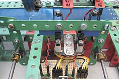
All electronic components and all needed plugs are mounted onto a breadboard, which
is situated between the cylinders.
|

The assembled Breadboard
|

The Cylinders with the
suggested Control Boxes
|
The photo transistor of the light barriers seems to have a fairly small angular
acceptance and therefore is relatively insensitive to ambient light - in any case
a normal room lighting has no affect to the operation.
In the sence of a reliable function (and of course for optical reasons) the
complete control unit is covered by a box, which protects the control against
excessive ambient light.
|
After completion and adjustment the machine works quite satisfactory, but needs
for that a supply voltage of at least 10 V (better is 12 to 13 V), from which
approx. 1 V drops at the MR501.
From about 12 V supply voltage also with warm coils the machine has a sufficient
reserve.
In this relation also the power consumption of the model is to consider:
Every coil has a resistance of approx. 10 Ohms. Because the switching times of
the coils overlap and for times 2 coils are active simultaneously, the power supply
should be able to provide a current of at least 2 A.
|

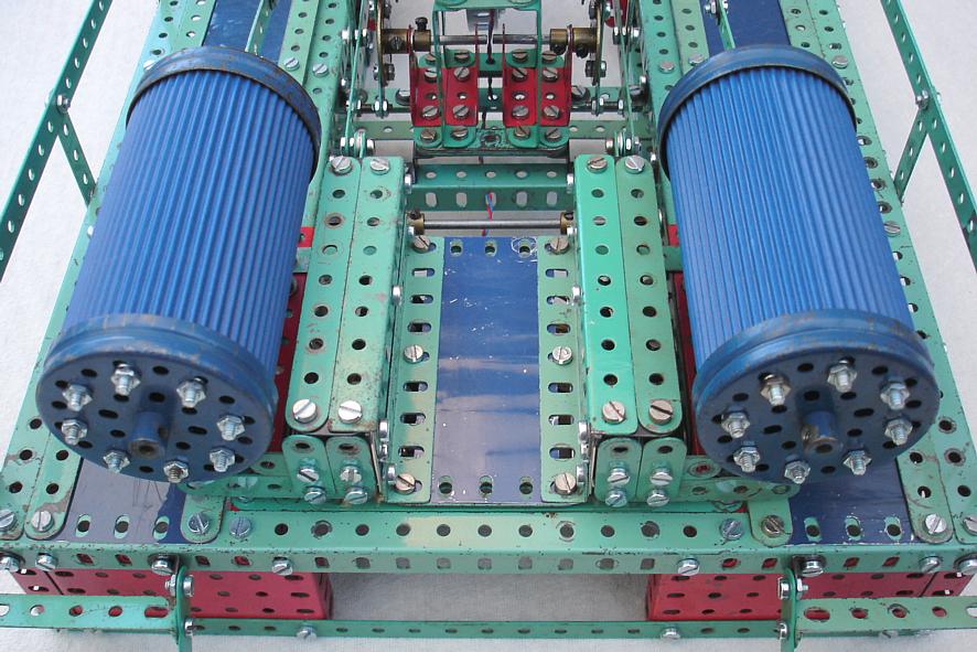
The 2 Cylinder Steam Engine with Link Motion
from another View
|

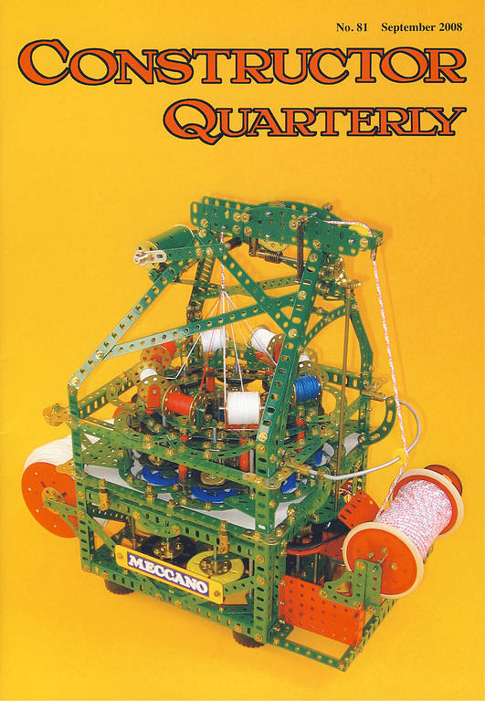
Deckblatt der Constructor Quarterly No. 81
|
Die Ausgabe No. 81 (September 2008) der englischsprachigen Zeitschrift
Constructor Quarterly enthält einen umfassenden Beitrag über die
2-Zylinder-Dampfmaschine mit Kulissensteuerung.
Die Abbildung der Titelseite dieses Heftes erfolgt mit freundlicher Genehmigung des
Herausgebers der Zeitschrift Constructor Quarterly.
|
And finally we present a
Video of the 2 Cylinder Steam Engine with
Link Motion (60s / 7,81MB)
Data of the 2 Cylinder Steam Engine with Link Motion:
| Length: | 51cm |
| Width: | 32cm |
| Heigth: | 22cm |
| Weigth: | 4kg |
| Number of Parts: | not yet counted |
Home
|